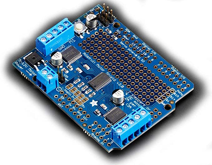
– A product for Arduino that works with official Arduino boards.
– This is a i2c-controlled PWM driver board with a built-in clock? which is quite different from TLC5940 series. You don’t need to continuously send signals and occupy your MCU.
– 5V compatibility, which means that you can use 3.3V MCU to control and drive the output up to 6V (when you want to control the white or blue indicator light, 3.4V+ is also OK).
– 6 address select pins allow you to connect 62 driver boards to one i2C bus, total 992 channels of PWM output.
– About 1.6KHz frequency modulation PWM output.
– Get 12-bit resolution output ready for stepping motor, which means that the 60Hz update rate can reach to 4us resolution.
– Configurable totem-pole output or open-collector output.
– Output enable pin can quick disable all outputs.
– PCA9685 chip is at the center of the board.
– With power input terminal.
– With green power indicator light.
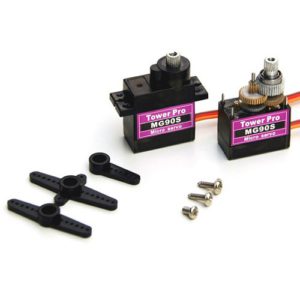
– Convenient to insert total 16 servos at the same time (the plug of servo is a little large than 0.1″, so you can put 4 pairs of 0.1″ connectors).
– With reverse polarity protection for input.
– Cascade design.
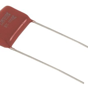
– Put a bulky capacitor on the V+ line (sometimes you need it).
– Put 220 ohm resistance components onto all PWM output lines, so as to protect them, and you can easily drive the LED.


There are no reviews yet.